
Aerospace · Reverse engineering
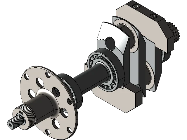
Aeronca E-113A Crankshaft
A legacy rotating assembly reconstructed into a coherent digital definition for engineering review and downstream documentation.
01Defined challenge
02Visible approach
03Controlled next step
The challenge
Make the engineering problem visible
Legacy aerospace components can arrive with incomplete drawings, difficult-to-measure interfaces, and geometry that reflects historical manufacturing methods. The immediate need is a reliable model without pretending that undocumented design intent is known.
Approach
Structure the work around decisions
- Organize available reference information and identify missing dimensions.
- Reconstruct the primary shaft, bearing, flange, and interface geometry in a controlled assembly.
- Separate measured facts from assumptions that require engineering confirmation.
- Prepare the model structure for drawings, fit checks, and revision.
The reconstructed assembly gives reviewers a common visual and geometric reference. It also creates a clearer path for tolerance review, material confirmation, inspection planning, and future manufacturing decisions.
Portfolio note
Project spotlights describe the engineering scope visible in the supplied portfolio material. Detailed client data and confidential performance results are intentionally omitted.
Related capability: 3D Engineering Design.
Start a project
Put your project on the board.
Aurea can begin from a sketch, a legacy part, an existing model, or a production problem. The first task is defining what must be learned next.