
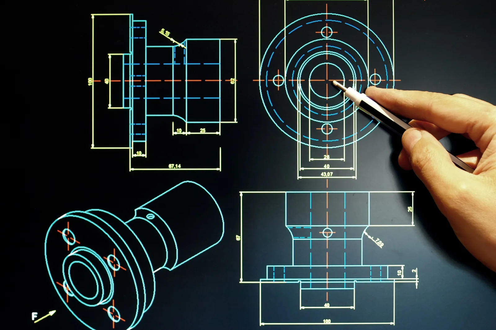

# Engineering Drawings and Tolerances: The Language That Prevents Manufacturing Errors
A three-dimensional model can show the shape of a part with remarkable clarity. It does not automatically tell a manufacturer which variation is acceptable, which surfaces control assembly, what material and finish are required, how a feature should be inspected, or which revision is approved.
That is the role of the engineering definition. In many product-development environments, controlled 3D models, 2D engineering drawings, specifications, bills of materials, and change records work together to communicate design intent.
When that language is incomplete or ambiguous, suppliers fill gaps with assumptions. Different suppliers may make different assumptions. Production, inspection, assembly, and service can each interpret the same part differently. The result may be rework, delayed quotes, unnecessary cost, inconsistent fit, or disputes about whether a delivered part is acceptable.
Good drawings do not attempt to describe every imaginable fact. They communicate the information required to make and verify the product consistently.
A drawing is a contract for design intent
An engineering drawing should let a competent manufacturer understand what item is required and let quality personnel determine whether the item meets the released definition. It should be consistent with the associated model, specification, and bill of materials.
The drawing commonly identifies the part or assembly, number, title, revision, units, scale, projection, material, finish, general tolerances, applicable standards, views, dimensions, feature controls, notes, and approvals. The exact content depends on the product, process, company system, and governing standards.
Treat the released drawing as controlled information. Drafts and reference exports should be clearly distinguished from production releases. If a supplier receives several files with different dates and no authoritative revision, configuration risk exists before manufacturing begins.
The drawing is not a substitute for communication, but it should remain understandable after the meeting and email thread are gone.
Begin with function and interfaces
Before adding dimensions, identify what makes the part work.
Which surfaces locate the part? Which holes align it? Which faces seal, slide, support, clamp, or transfer load? Which features are cosmetic? Which dimensions control user interaction, assembly clearance, tooling access, or interchangeability? What can vary without consequence?
This functional map guides the drawing. Critical interfaces deserve clear definition and appropriate control. Noncritical geometry should not inherit expensive precision by accident.
For assemblies, define how parts relate and which item owns each interface. If two teams dimension mating parts from unrelated origins without managing the stack, each drawing may look complete while the assembly remains uncertain.
Drawings become more effective when the designer can explain the reason behind each critical requirement. That rationale should be preserved in requirements, calculations, design reviews, or other engineering records even if it does not all appear on the drawing.
Dimensions describe nominal geometry; tolerances describe acceptable variation
No manufacturing process produces an exact mathematical size or shape. Tolerances define the variation the design can accept.
A size may be expressed with bilateral limits, unilateral limits, limit dimensions, or through a general tolerance system where appropriate. Geometric controls may define form, orientation, and location relative to datums. Surface texture, edge conditions, and process notes may control other characteristics.
The tolerance should come from function and manufacturing knowledge. A designer should not tighten a value simply to appear precise or because the CAD model shows many decimals. Extra decimal places can imply control that the product does not need and the process cannot economically provide.
The opposite is also true. A generous default tolerance may be inadequate for a bearing fit, seal compression, gear center distance, alignment, or visible gap. The team must understand the assembly and expected variation.
Treat tolerances as an allocation problem
An assembly requirement is often influenced by several parts and features. Tolerance analysis allocates allowable variation so the system can function.
Consider a gap controlled by a frame, spacer, cover, and fastener location. Tolerancing each drawing independently can consume more variation than the gap allows. A stack analysis connects the component dimensions to the assembly result.
Worst-case analysis assumes every contributing feature reaches the combination that produces the largest or smallest result. It is conservative and appropriate when every allowable assembly must satisfy the requirement. Statistical approaches can reflect the low probability of all features reaching extremes together, but they require knowledge of process distributions, centering, independence, production control, and risk.
Do not choose a method only because it produces a comfortable number. State the assumptions, data, and consequence of failure. Validate the stack through inspection and assembly evidence as the product matures.
Datums create a shared frame of reference
Datums identify theoretically exact references from which geometric relationships are established. Practical datum features on the part—such as a surface, hole, or pattern—help define how the part is oriented for function, manufacture, and inspection.
A useful datum reference frame often reflects how the part locates in the assembly. The primary reference constrains the first degrees of freedom, followed by secondary and tertiary references. The exact scheme depends on the geometry and applicable standard.
Poor datum selection can make a drawing difficult to manufacture or inspect. A small unstable surface may not provide a repeatable reference. A datum unrelated to assembly may control features accurately to the wrong thing. Competing datum schemes across drawings can complicate fixtures and measurement.
Discuss datums with manufacturing and quality. A functional datum system should also be practical to simulate in inspection.
What GD&T adds
Geometric dimensioning and tolerancing, or GD&T, is a standardized symbolic language for controlling form, orientation, location, profile, and runout. It can communicate functional requirements more clearly and sometimes more economically than coordinate tolerancing.
For example, position can control the location of a hole pattern relative to a datum reference frame while allowing a tolerance zone suited to the cylindrical feature. Profile can control a surface relative to datums. Flatness can control a surface without referencing another feature. Perpendicularity can control orientation.
GD&T is powerful because it separates different kinds of variation and relates control to function. It is also easy to misuse. A symbol should not be added because it looks sophisticated. The designer, manufacturer, and inspector need a common understanding of the applicable standard and feature control frame.
Material condition modifiers, datum modifiers, composite controls, projected zones, and other advanced tools can be valuable, but they should be selected by someone competent in their use. Ambiguous or conflicting controls can make a drawing more expensive and less reliable.
Avoid overdimensioning and conflicting requirements
A feature should be defined clearly without multiple independent dimensions that fight each other. Reference dimensions can communicate useful information, but they should be identified as reference and not create an additional acceptance requirement.
Common problems include dimensions repeated in several views, a chain of dimensions plus an overall dimension with no stated reference status, model values that disagree with drawing values, and general tolerances that conflict with specific notes.
Choose dimension origins and schemes intentionally. Baseline or ordinate approaches can control accumulated variation differently from chained dimensions. The best scheme depends on function and manufacturing.
Before release, review the drawing as a logical system. Ask whether every requirement can be satisfied simultaneously and whether the acceptance interpretation is unique.
Define materials and finishes unambiguously
A generic callout such as “aluminum” or “plastic” is rarely enough for a controlled production part. Grade, condition, form, color, additives, treatment, and applicable specification may affect performance and manufacturing.
Finishes require similar clarity. Define the process, specification, class or type, color, thickness where relevant, masking, surface preparation, appearance zones, and post-treatment requirements as applicable. Consider whether dimensions apply before or after coating.
Avoid specifying a process when only the performance matters unless the process is intentionally controlled. Conversely, do not describe performance so loosely that the supplier can choose a materially different result.
Make substitutions an approval process. If equivalents are permitted, define the criteria and who approves them. Record the approved change in the controlled definition rather than leaving it in purchasing correspondence.
Use notes carefully
Notes are useful for requirements that do not fit cleanly into dimensions or feature controls: deburring, cleaning, marking, workmanship, special processes, testing, packaging, or referenced specifications.
A note should be specific, necessary, and verifiable. “Remove all sharp edges” may be reasonable in context but can be interpreted differently unless edge requirements are defined. “No scratches” may be impractical without cosmetic zones, viewing conditions, and acceptance limits. “As required” transfers the design decision to the supplier.
Do not hide critical design requirements in a long block of boilerplate. Place notes logically, eliminate obsolete template language, and confirm that referenced documents are available and current.
When a note applies only to one feature, attach it to that feature rather than relying on the reader to infer scope.
Make inspection possible
Every acceptance requirement implies a measurement or evaluation method, even if the method is not always specified on the drawing.
Ask how the supplier will hold, orient, access, and measure the part. A deep internal feature may require specialized equipment. A flexible component may need a defined restraint condition. A surface profile may require a fixture and data alignment. A cosmetic evaluation needs controlled viewing conditions.
Measurement uncertainty should be suitable for the tolerance. If the inspection method cannot distinguish conforming from nonconforming product reliably, the control system needs improvement. Gauge repeatability, calibration, sampling, environmental conditions, and operator method may matter.
For high-volume or critical features, functional gauges can evaluate the interface efficiently. Coordinate measurement can provide detailed data, but a sophisticated machine does not correct an unclear datum scheme or unstable part setup.
Collaborate with quality before final release, not after the first rejected lot.
Account for process capability
A tolerance is only useful if an appropriate process can hold it consistently. Manufacturing capability depends on equipment, tooling, material, geometry, setup, environment, maintenance, operator practice, and inspection.
Ask suppliers which features drive special operations, slow cycles, hand selection, or 100-percent inspection. A tolerance that one supplier holds routinely may exclude others. A feature near the edge of process capability may produce acceptable first articles but unstable production.
Capability data should be tied to the actual feature, process, and conditions. Generic claims about machine accuracy are not enough. Where risk justifies it, define first-article, capability, or control-plan evidence.
If the process cannot meet the requirement economically, the team can change the design, choose a different process, add a secondary operation, select parts, or accept the cost—with a documented understanding of the tradeoff.
Model-based definition and drawings can coexist
Some organizations use model-based definition, where product manufacturing information is embedded in a controlled 3D model. Others rely primarily on 2D drawings, and many use a hybrid.
The key is authority and completeness. Which file governs geometry? Where are tolerances and notes defined? How are annotations viewed? Which neutral formats are acceptable? How are revisions and derivatives controlled? Can suppliers and inspectors access the definition without losing information?
Do not allow the drawing and model to become competing authorities. A note such as “CAD model governs” is not sufficient if the released model is not identified, controlled, or available in a suitable format.
Choose the approach that fits the product, supply chain, tools, and quality system. Then document it consistently.
Assembly drawings and bills of materials
Part drawings define components; assembly information explains relationships.
An assembly drawing may show item balloons, views, sections, interfaces, fasteners, adhesives, torque, routing, adjustment, alignment, and inspection or test steps. The bill of materials identifies part numbers, descriptions, quantities, revisions or effectivity as appropriate, and purchased items.
Confirm that every balloon maps to the bill and every bill item appears as intended. Avoid descriptions too vague to purchase the correct component. Identify approved manufacturer parts where interchangeability matters. Manage alternates deliberately.
Assembly requirements should be executable. If sequence matters, provide controlled work instructions or other documentation rather than expecting one exploded view to carry the entire process.
Revision control prevents invisible divergence
The technical definition will change. Revision control ensures that everyone knows which version is approved and why it changed.
A controlled change process identifies the problem or opportunity, affected items, rationale, technical review, disposition of existing inventory and work in progress, implementation date or effectivity, and approvals. Update every affected model, drawing, specification, bill, instruction, inspection plan, and supplier communication.
Do not overwrite released files silently. Do not use filenames such as “final-final-2” as configuration control. Do not assume that sending a new attachment causes every supplier location and production station to remove the old one.
For prototypes, mark parts so test results can be traced to revision and process. For production, maintain records appropriate to product risk and business obligations.
Common drawing failures
No functional datum strategy. Features are controlled from convenient model origins rather than assembly references.
Tolerances copied without analysis. Defaults become too tight for some features and too loose for critical ones.
Conflicting model and drawing. Suppliers do not know which authority to follow.
Vague material or finish. Different lots or suppliers produce materially different results.
Unmeasurable requirements. The drawing demands control without practical access, setup, or acceptance method.
Boilerplate notes. Old requirements remain from another product or conflict with the current design.
Missing revision communication. Production uses a technically obsolete but locally stored file.
Drawing as decoration. The document looks complete but does not express the interfaces and variation that determine function.
A practical release review
Before issuing a drawing for quote or production, ask:
- Is the part number, title, revision, unit system, and authority clear?
- Does the drawing agree with the released model and bill of materials?
- Are functional interfaces and critical characteristics identified?
- Do datums reflect assembly and allow repeatable inspection?
- Are dimensions complete without being duplicated or conflicting?
- Are tolerances traceable to function and appropriate to process capability?
- Are material, finish, marking, edge, and special-process requirements clear?
- Can each acceptance requirement be measured or evaluated?
- Are referenced standards and specifications current and accessible?
- Has manufacturing and quality reviewed the current revision?
- Are supplier exceptions resolved and incorporated?
- Is the change and release record complete?
Use a second reviewer who did not create the drawing. Familiarity makes assumptions invisible.
Clear drawings create repeatable decisions
Engineering drawings and tolerances do more than tell a supplier where to cut material. They connect product function to manufacturing variation and inspection evidence.
A strong definition gives manufacturers room where variation does not matter and clear control where it does. It reduces quote ambiguity, supports consistent inspection, makes changes traceable, and helps different suppliers produce interchangeable results.
The best drawing is not the one with the most dimensions or symbols. It is the one that communicates the design intent completely, economically, and without contradiction.
If your team is preparing drawings for supplier quote, prototype release, tooling, or production transfer, Aurea Engineering can help develop or review the engineering package, tolerance strategy, and manufacturing documentation. Resolve ambiguity before it becomes material, labor, and schedule.
> Editorial note: This article provides general educational information. Drawing and tolerancing practices depend on the governing standards, product, process, quality system, supplier, and risk. Qualified personnel should create and approve the final engineering definition.