
# 3D Printing vs. CNC Machining vs. Casting: Choosing the Right Prototype Process
Choosing a prototype process is not a contest between technologies. The right method is the one that answers the next engineering or business question with enough fidelity, at an acceptable cost and lead time.
A 3D-printed model may be ideal for checking packaging and user interaction. A CNC-machined part may be necessary to evaluate stiffness, threads, sealing, or behavior in a production-relevant metal. Urethane casting may make sense when a team needs several realistic-looking polymer parts without committing to injection tooling. A cast-metal prototype may be valuable when the manufacturing process itself influences the result—but it can be a poor first step if the design is still changing.
The mistake is asking, “Which process makes the best prototype?” before asking, “What must this prototype prove?”
Define the prototype’s job
Every prototype should have a written purpose. Common purposes include:
- Evaluating size, proportion, and product architecture.
- Testing user reach, grip, installation, or maintenance access.
- Proving a mechanism or physical principle.
- Measuring strength, stiffness, heat, flow, vibration, sealing, wear, or life.
- Checking interfaces between components or disciplines.
- Demonstrating appearance for stakeholder or market feedback.
- Developing assembly steps, fixtures, inspection, or packaging.
- Producing limited quantities for controlled field evaluation.
- Assessing a production process before tooling or release.
One prototype rarely does all of these well. A model optimized for appearance may use materials that invalidate structural tests. A fast mechanism rig may expose moving parts and ignore enclosure constraints. A production-intent sample may be too expensive and slow for early architecture changes.
Write the question, configuration, measurement, acceptance criteria, and next decision before selecting the process. The process should follow that definition.
The major selection factors
Compare candidate methods across the characteristics that matter for the specific test.
Material behavior
Does the prototype need the final material, a material from the same family, or only approximate stiffness and weight? Consider anisotropy, temperature, creep, impact, fatigue, friction, moisture, chemicals, optical behavior, conductivity, and finish—not just nominal tensile strength.
Geometry and scale
Thin walls, deep cavities, internal channels, overhangs, undercuts, large envelopes, fine features, and closed volumes affect process suitability. Some processes make complex geometry easily but struggle with broad flatness or surface. Others provide precision but require tool access.
Accuracy and surface
Which dimensions and interfaces must be representative? A prototype can be accurate overall while its holes, threads, seals, or mating faces require secondary work. Surface roughness may influence friction, leakage, appearance, coating, or user perception.
Quantity
One part, ten parts, and hundreds of parts create different economics. Setup, programming, patterns, molds, post-processing, and inspection may dominate small quantities. Repeatability becomes more important as quantity grows.
Lead time and change cost
How quickly can the team receive the first article? More importantly, how quickly and cheaply can it incorporate what the test reveals? A process with a low first-part price can become expensive if every change requires a new tool.
Evidence needed
Will the part be measured, loaded, cycled, presented, assembled, or used in a formal verification activity? Define how differences from the final design affect the conclusion.
3D printing: speed and geometric freedom
“3D printing” includes processes with different materials and behavior. Fused filament fabrication, stereolithography, selective laser sintering, multi-jet fusion, and metal powder-bed processes should not be treated as interchangeable.
Where it is strong
Additive manufacturing is often excellent for rapid geometry iteration, packaging models, ergonomic studies, complex ducts or internal paths, assembly checks, fixtures, and low-quantity parts. It can produce shapes that would require multiple machined components or impossible tool access. Digital changes are relatively fast because no hard tool is required.
Polymer processes offer different tradeoffs. Filament parts can be economical and fast but show layer-dependent strength and surface. Resin processes can provide fine detail and smooth appearance but may be brittle or sensitive to environment. Powder-bed polymer parts can provide complex, self-supporting geometry and useful durability, though surface and dimensional behavior differ from molded material.
Metal additive manufacturing can create complex high-value parts, but it brings substantial process, support, thermal, post-machining, inspection, and qualification considerations. It is not simply a metal version of desktop printing.
Where it can mislead
Printed material properties may differ from production material. Build orientation, layer adhesion, porosity, cure, and surface can influence test results. Thin features may warp. Holes and threads may require machining or inserts. Broad cosmetic surfaces may need significant finishing. A printed snap, living hinge, seal interface, or heat-exposed part may not represent a molded equivalent.
If a functional test uses a printed part, document the process, machine, material, orientation, parameters, post-processing, and deviations. Otherwise, a later team cannot understand what the result means.
Best questions for 3D printing
- Does the geometry fit and assemble?
- Can a user reach, grip, see, or install it?
- Does a low-load mechanism move as intended?
- Is an internal path or complex shape worth pursuing?
- Which of several geometry variants should advance?
CNC machining: precision and production-relevant materials
CNC machining removes material from stock using controlled tools. It can produce accurate parts in many common metals and engineering plastics without dedicated hard tooling.
Where it is strong
Machining is valuable when material behavior, threads, sealing faces, bearing fits, flatness, stiffness, heat transfer, or accurate interfaces matter. It can support functional assemblies and provide parts closer to many final material specifications. For low volumes, it may also be the intended production process.
Machined prototypes can be inspected using methods similar to production. Surface finishes and secondary operations can approximate final requirements. Changes may require new programming or setup but not a new mold.
Where it can mislead
A machined prototype may not represent a future molded, cast, forged, or formed part. Machining can create uniform properties and sharp control that the production process will not reproduce. A part cut from billet may pass a load test even though a cast version has different section behavior, porosity, grain, or defects. A machined plastic part may behave differently from a molded part because of material form, stress, or anisotropy.
Machining also imposes tool-access and workholding constraints. Deep pockets, internal corners, thin walls, multiple orientations, and complex surfaces increase cost. Designers should not conclude that a geometry is production-ready merely because a skilled machine shop made one expensive sample.
Best questions for CNC machining
- Do critical fits, threads, seals, and interfaces work?
- How does a production-relevant material behave under load or heat?
- Can the team assemble and test an accurate functional unit?
- Is the part suitable for low-volume machined production?
- Which tolerances are necessary based on measured performance?
Urethane casting: small batches with molded-like appearance
Urethane or vacuum casting commonly uses a master pattern to create a flexible mold, then casts polyurethane parts. It can bridge the gap between one-off models and hard production tooling.
Where it is strong
This process can produce small batches with consistent appearance, color, texture, and geometry. It is useful for stakeholder samples, user evaluations, controlled field units, and assemblies that need multiple similar polymer parts. Inserts and certain finishes can be incorporated depending on supplier capability.
Because tooling is softer and less expensive than production injection tooling, changes may be more manageable. The process can provide a presentation level that raw additive parts do not achieve without extensive finishing.
Where it can mislead
Cast urethanes are material analogs, not automatically equivalent to production thermoplastics. Mechanical, thermal, chemical, aging, and flammability behavior may differ. Flexible molds have limited life and can introduce variation over repeated shots. Wall thickness and geometry that work in urethane casting may still violate injection-molding guidelines.
Use these parts for the questions their material and process can support. Do not use a visually realistic sample as proof that the final molded product has been structurally or environmentally validated.
Best questions for urethane casting
- How do several representative-looking units assemble and present?
- What do users think of the size, texture, and interaction?
- Can the team run a small controlled evaluation before production tooling?
- Are color, finish, labeling, and packaging directions credible?
Metal casting: process-relevant prototypes and preproduction learning
Metal casting includes multiple processes such as sand casting, investment casting, permanent-mold casting, and die casting. Their tooling, accuracy, surface, section limits, alloys, and economics vary widely.
Where it is strong
A cast prototype can provide evidence about the real process: filling, solidification, draft, parting, gates, risers, shrinkage, porosity, section transitions, and required machining. It can support material and geometry evaluation when casting is central to production.
Some casting methods use lower-cost patterns or tooling suitable for development quantities. Others make sense mainly near production volumes.
Where it can mislead
One successful casting does not prove stable production. Process windows, tooling, supplier practice, lot variation, heat treatment, and inspection matter. Prototype tooling may not reproduce the thermal behavior or cycle of production tooling. Material properties depend on alloy, process, heat treatment, location, and defects.
Casting too early can slow learning if the architecture is still moving. Before committing, confirm that the prototype must answer a casting-specific question that machining or additive methods cannot answer credibly.
Best questions for casting
- Can the proposed geometry be filled and solidified with acceptable risk?
- Where are machining and inspection allowances required?
- How do section transitions, draft, parting, and gating affect the design?
- What process controls and evidence will production require?
Soft tooling and bridge injection molding
When injection molding is the intended process, prototype or bridge tooling can produce parts in production thermoplastics and reveal molding-specific behavior. Tooling may use aluminum or other approaches selected for lower volume and shorter life than full production tooling.
This route can be valuable for snap fits, living features, ribs, bosses, surface, assembly, environmental testing, and controlled builds. It can also support early sales or pilot quantities when the design is stable enough.
The tradeoff is commitment. Tooling costs more and takes longer than many prototype processes, and changes can require rework or replacement. Tool architecture, cooling, cavity count, gate strategy, and press conditions may differ from mature production. Treat bridge tools as part of the learning plan, not an excuse to skip DFM and validation.
Fabrication and hybrid prototypes
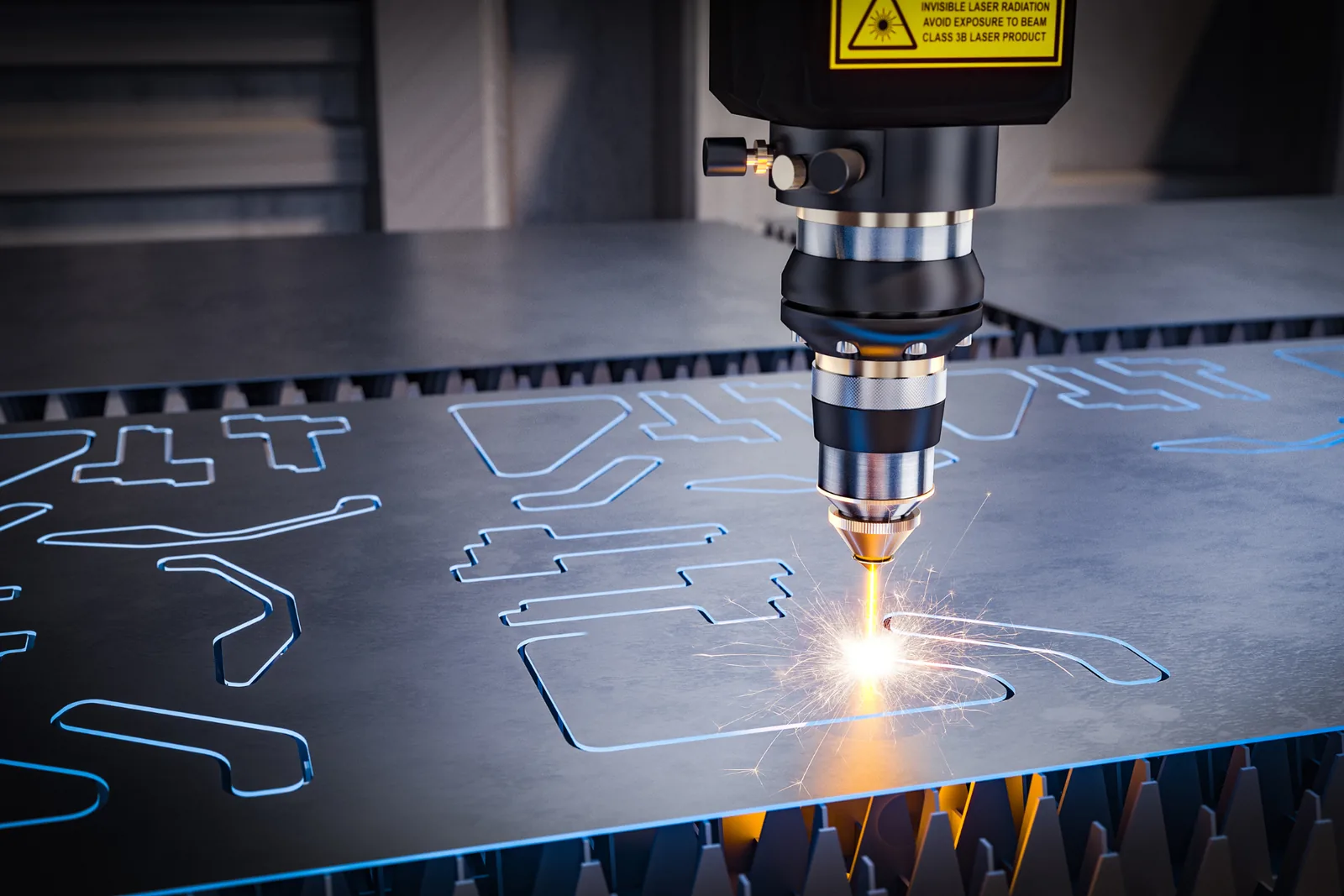
Some of the best prototypes combine processes. A team might machine critical bearing interfaces, print ducts and covers, laser-cut a frame, use catalog hardware, and cast a cosmetic shell. Hybrid builds put fidelity where the test needs it and save cost elsewhere.
Fabrication processes—sheet cutting and bending, welding, extrusion framing, sewing, bonding, turning, or manual assembly—can create robust rigs and representative structures quickly. Off-the-shelf components can replace custom parts until the architecture is stable.
Document every substitution. If prototype mass, stiffness, friction, or geometry differs, state how that difference affects the test. Hybrid does not mean uncontrolled; it means intentional allocation of fidelity.
A practical process-selection matrix
Use a matrix as a conversation tool rather than a universal scorecard.
| Question | Often useful starting method | Important caution | |---|---|---| | Packaging and appearance | Polymer 3D print, finished model | Material and finish may not represent production | | Ergonomics | 3D print, foam/modelmaking, fabrication | Include representative mass and interfaces when relevant | | Accurate metal interfaces | CNC machining | May not represent cast or formed production behavior | | Complex internal flow path | Additive manufacturing | Surface and material can change flow or heat results | | Small batch of realistic polymer housings | Urethane casting | Urethane is not the final thermoplastic | | Injection-specific function | Bridge injection tooling | Higher change cost; design should be reasonably stable | | Casting feasibility | Appropriate prototype casting method | One casting does not prove production capability | | Integrated engineering unit | Hybrid build | Configuration control is essential |
Supplier capability can change the answer. Review the actual geometry, material, tolerance, quantity, test, and schedule with qualified suppliers.
Compare total prototype cost
The quoted part price is only one component. Include design adaptation, programming, tooling or patterns, setup, material, finishing, secondary machining, inserts, inspection, shipping, assembly, test fixtures, and the cost of a change.
Also consider the cost of weak evidence. A low-cost part that cannot support the intended test may delay the program or create a false conclusion. A high-fidelity part may be wasteful if a simple rig could answer the decision in two days.
Ask how many learning cycles the budget can support. Early development often benefits from several fast, focused iterations rather than one expensive integrated build.
Control configuration and testing
Whatever process you choose, trace the physical prototype to its definition. Record revision, material, supplier, process, orientation where relevant, post-processing, deviations, inspection, and test history. Label parts and assemblies.
Create a test plan before the prototype arrives. Define sample quantity, conditioning, equipment, method, data, acceptance criteria, and disposition. Separate exploratory testing from formal verification. Preserve failed parts when they contain useful evidence.
After testing, decide what changes, what remains open, and which conclusion the prototype supports. Update the risk register and development plan.
Choose evidence, not technology
3D printing, CNC machining, and casting are tools. None is automatically the fastest, cheapest, strongest, or most realistic for every product. The right process is determined by the decision the team needs to make.
Before requesting a quote, answer:
- What exactly must the prototype prove?
- Which dimensions, materials, surfaces, and behaviors must be representative?
- Which differences from production are acceptable?
- How will the result be measured?
- How many iterations or units are likely?
- What decision follows a pass, failure, or ambiguous result?
If your team is deciding between prototype methods or preparing an integrated engineering build, Aurea Engineering can help define the test purpose, select appropriate fidelity, and translate results into controlled design decisions. The most valuable prototype is not the one that looks most finished; it is the one that produces the evidence your next decision requires.
> Editorial note: This article provides general educational information. Prototype properties and process capability vary by machine, material, supplier, geometry, post-processing, and test conditions. A qualified engineer and appropriate supplier should review the specific application.